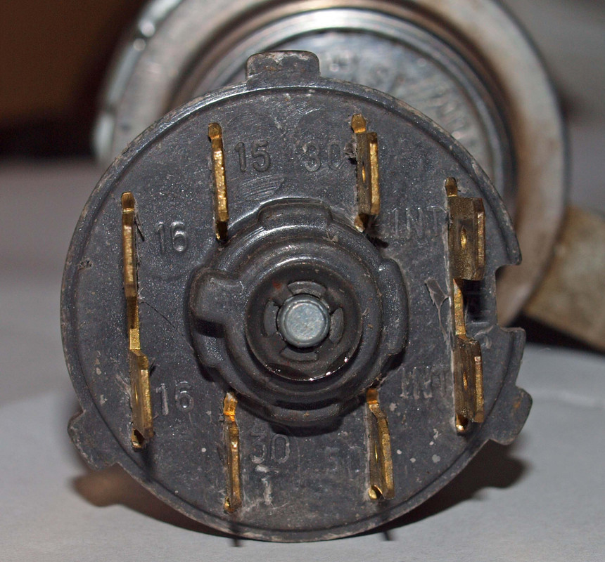
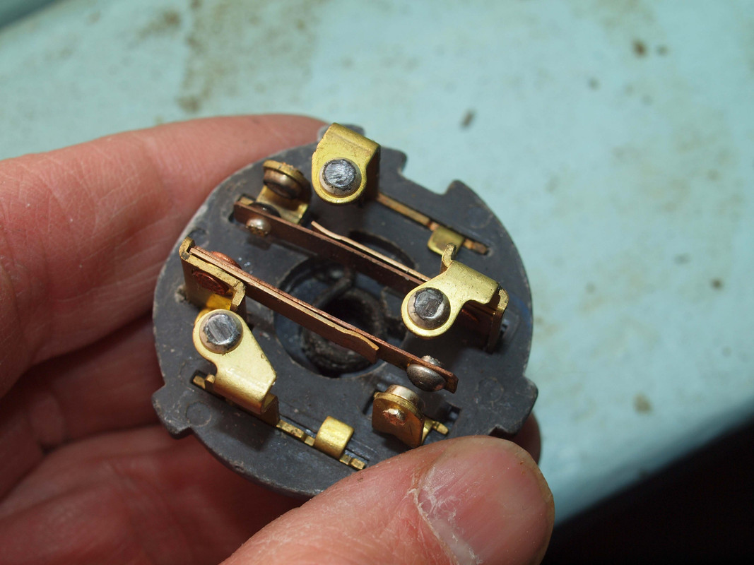
My confusion is the fact there seems to be 2 power feeds to the switch, the Black wire (30/1 terminal, source the alternator) and the Brown wire (30 terminal, source the starter motor). Why is this?
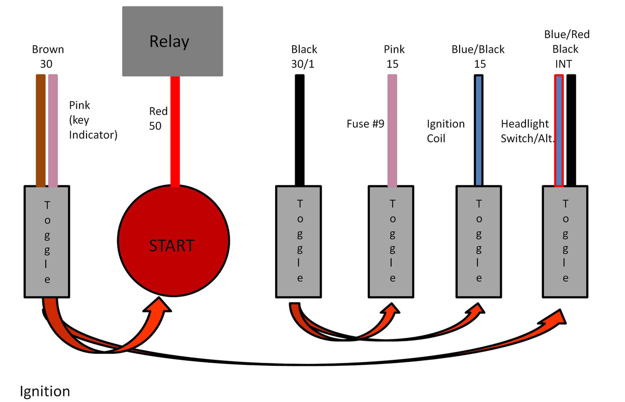
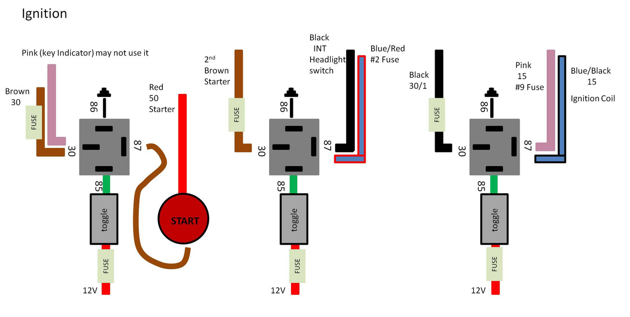
I have created my first draft on the push button system:
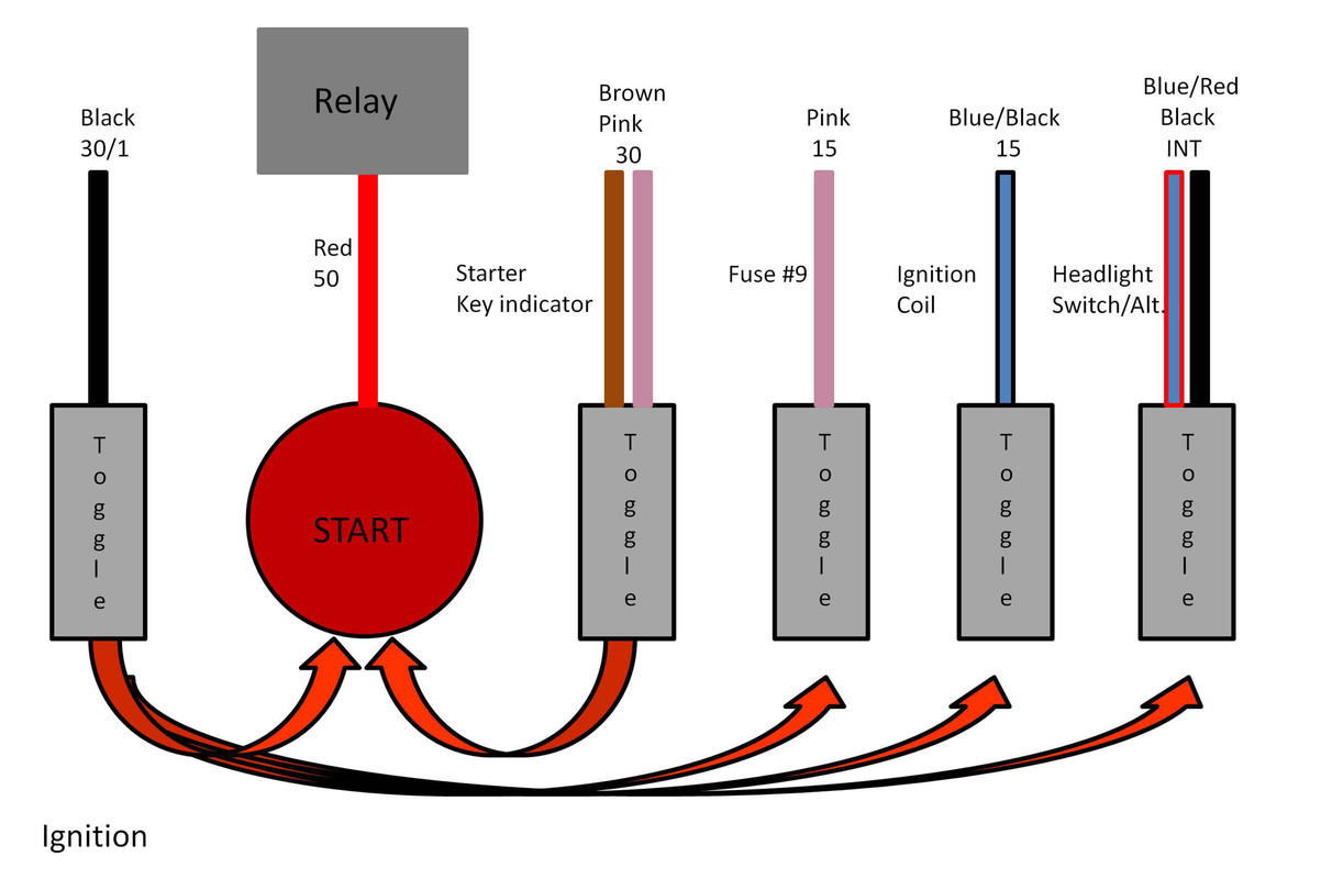
In the diagram I try to simulate the black and brown connecting in the "on" position as with the Fiat ignition switch.
My confusion is how do I deal with the brown wire? Is the diagram a good solution? Is the brown wire vital to the operation of the system or can I simply eliminate it? To me it seems redundant to have 2 12v inputs. Maybe I am to stupid to see the reason, it is just all my other classic cars (Ford) do not have a wire running from the starter to the ignition switch. Thier approach is a starter relay and the wire from the starter goes to the relay and then a wire goes from the relay to the ignition switch (simple).
I know most of you do not like this idea but it could be an inexpensive and reliable solution seeing how there seems to be no more Sipea switches left. All I need to do is figure out the wiring.
Thanks for reading.